Plastic Injection Molding Parts: Design & Production Guide
You're probably in a familiar spot. The CAD is mostly done, the industrial design team wants cosmetic samples, purchasing wants a realistic quote, and test engineers are asking whether the first plastic enclosure will behave anything like the production part. Everyone says “just injection mold it,” but the hard part isn't choosing the process. It's choosing the right point to commit.
That tension shows up everywhere in product development. A robotics team may need housings that snap together cleanly. A medical device group may need traceability and repeatable geometry. An automotive supplier may need parts that survive assembly loads and still look good after finishing. In each case, the same question appears: when do you stay in prototype mode, and when do you move into real plastic injection molding parts?
The scale of the process explains why teams keep returning to it. The global injection molded plastics market reached USD 358.71 billion in 2025 and is projected to reach about USD 511.9 billion by 2035, with a CAGR of 3.62%. That size reflects a simple reality. Injection molding remains one of the most dependable ways to make large quantities of consistent plastic parts.
Table of Contents
- Introduction to Plastic Injection Molding Parts
- Understanding Injection Molding Components
How the plastic gets into the part
The terms that confuse people first
Choosing Materials for Injection Molding Parts- Material choice starts with part behavior
Applying DFM Rules and Tolerance Guidelines- The geometry rules that prevent expensive defects
Comparing Prototyping and Low Volume Workflows- Why one prototype process rarely answers every question
Analyzing Cost Drivers and Lead Times- Why small batches surprise teams
Implementing Finishes Inspections and Quality Pathways- Finishes need to support use, not just appearance
Conclusion Partnering with FIRMFG
Introduction to Plastic Injection Molding Parts
A senior engineer once described injection molding to a new hire this way: machining lets you carve one answer at a time, but molding lets you repeat the answer thousands of times. That's why so many teams use CNC, SLA, or vacuum casting for learning, then turn to molding when the part has to become stable, repeatable, and supply-chain ready.
Plastic injection molding parts matter most when three conditions show up together. The geometry is too complex for cheap fabrication by hand. The quantity is high enough that repeatability matters. The product also needs features such as snaps, bosses, ribs, texture, or integrated mounting details that are hard to add efficiently later.
For engineers, the challenge isn't understanding that molding is powerful. The challenge is understanding when the part design is ready for it. A battery cover that looks simple on screen may hide thick-to-thin transitions, sharp corners, poor gate options, and cosmetic surfaces that fight each other. A handheld enclosure may pass a fit check in SLA and still fail in molded resin because the wall layout was never designed for shrinkage and cooling.
Practical rule: Treat injection molding as a system, not a machine. Part shape, resin choice, tool design, finishing, and inspection all affect the final result.
Teams also get misled by “rapid” language. Rapid tooling can shorten the path to molded parts, but it doesn't remove the need for design discipline. If the geometry is weak, the process reproduces the weakness faster.
That's why the best results usually come from a staged approach. Validate shape and interfaces first. Lock material intent next. Apply DFM rules before tooling. Then choose the lowest-risk path into pilot quantities and low-volume production.
Understanding Injection Molding Components
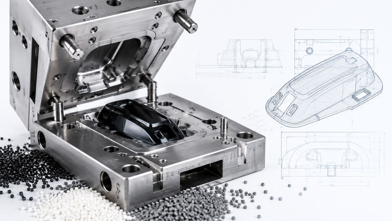
Injection molding can feel mysterious until you break the machine and mold into a few basic functions. Pellets go in. Heat softens them. Pressure moves the melt into a shaped cavity. Cooling hardens the part. Ejection removes it. That cycle repeats with remarkable consistency when the part and mold are designed well.
The process dominates large-scale plastic manufacturing. Plastic injection molding production volume was valued at 157.13 million tons in 2025 and is forecast to reach 201.47 million tons by 2031. Engineers don't need that figure to run a mold trial, but it's a good reminder that this process became standard for a reason.
How the plastic gets into the part
Think of the mold like a network of small channels feeding a shaped pocket.
- Hopper: The machine stores plastic pellets here before they enter the barrel.
- Barrel and screw: Heat and screw motion melt and push the resin forward.
- Sprue: This is the main passage from the machine nozzle into the mold.
- Runner: Runners distribute molten plastic from the sprue toward one or more cavities.
- Gate: The gate is the controlled opening where melt enters the part.
- Cavity and core: These surfaces create the part's outer and inner geometry.
- Ejector system: Pins or plates push the cooled part out after the mold opens.
A cookie-cutter analogy helps. The cavity is the shape you want. The runner system is how the dough reaches it. The gate is the final narrow opening that controls the fill.
The terms that confuse people first
New engineers often hear machine terms before they understand what they influence.
| Term | Plain meaning | Why it matters |
|---|---|---|
| Clamp force | The force holding the mold shut | Too little force can let the mold separate during filling |
| Shot size | The amount of plastic injected in one cycle | It has to cover the cavity and flow path consistently |
| Cycle time | The time to mold one complete part | It affects throughput, cost, and temperature stability |
The part's geometry drives much of the process behavior. A deep rib may be easy to model but hard to fill cleanly. A cosmetic face may need the gate moved to hide vestige or flow marks. A snap feature may need draft and radius adjustments so the tool can release the part repeatedly without damage.
Good molding isn't just about forcing plastic into a cavity. It's about helping the plastic flow, cool, shrink, and eject in a controlled way.
Once you see the components as a flow system rather than a black box, mold reviews become much easier to follow.
Choosing Materials for Injection Molding Parts
Material selection often goes wrong for a simple reason. Teams choose resin by habit instead of by part behavior. They say “use ABS” because the last housing used ABS, or “use nylon” because the part needs strength, without asking what kind of strength, what environment, or what finishing and inspection plan the part will face.
Material choice starts with part behavior
Start with the job the part has to do.
If the part is a consumer enclosure, ABS is often considered because it balances appearance, toughness, and moldability. If impact resistance and transparency matter more, polycarbonate becomes a candidate. Nylon enters the discussion when wear resistance or mechanical loading matters. Polypropylene is useful when flexibility or living hinge behavior matters. PEEK sits in a very different category and is usually reserved for demanding thermal or chemical environments.
The next distinction is structural. Amorphous materials such as ABS and polycarbonate generally behave differently from semicrystalline materials such as nylon and polypropylene. In practice, that affects shrink behavior, dimensional predictability, and how forgiving the material feels during development.
For a broader overview of processing behavior across common resins, this guide to injection molding thermoplastics is a useful reference.
Comparison of Common Injection Molding Materials
| Material | Key Properties | Typical Applications | Cost per kg |
|---|---|---|---|
| ABS | Tough, good cosmetic finish, easy to process | Consumer housings, brackets, covers | Varies by grade and supplier |
| Polycarbonate | High impact resistance, optical potential, durable | Guards, lenses, robust enclosures | Varies by grade and supplier |
| Nylon | Wear resistance, good mechanical performance | Gears, clips, functional components | Varies by grade and supplier |
| Polypropylene | Flexible, chemically resistant, hinge-friendly | Containers, lids, living hinges | Varies by grade and supplier |
| PEEK | High heat and chemical resistance | Demanding industrial and medical uses | Varies by grade and supplier |
When regrind is acceptable
Regrind gets oversimplified. Some teams assume it always weakens parts. Others assume it's harmless if the resin looks clean. Neither position is disciplined enough for engineering use.
Thermoplastic studies show that ABS and polycarbonate can maintain over 90% of original tensile strength with up to 15% regrind when strict moisture control is applied. That matters because it shifts the discussion from opinion to process control.
Ask practical questions instead of general ones:
- What resin family is being reground
- How is moisture being controlled
- Is the supplier separating virgin and reground streams
- Can the team verify consistency through incoming or process checks
For regulated or high-trust applications, teams may decide to avoid regrind entirely. That isn't always a material science issue. Sometimes it's a documentation and traceability decision.
Applying DFM Rules and Tolerance Guidelines
Many part failures blamed on molding begin in CAD. The machine reveals them. If the geometry fights flow, cooling, and ejection, the toolmaker can only do so much.
A useful first filter is this: if a feature looks easy to machine but awkward to release from a mold, pause and review it. Plastic injection molding parts reward balanced geometry, not just precise geometry.
The geometry rules that prevent expensive defects
The most important DFM rule is wall consistency. According to design guidance for injection molded plastic parts, wall thickness should remain within 25% of the base wall thickness, with a minimum allowable wall thickness of 0.4 mm and typical wall ranges around 1.2 to 1.7 mm, depending on section type. When walls swing too far from that baseline, parts become more likely to show uneven shrinkage, warpage, sink, bubbles, and internal stress.
Here's the checklist many teams should review before tooling:

- Wall thickness: Keep sections consistent instead of alternating between thin skins and heavy blocks.
- Draft: Vertical faces need release help. Without draft, ejection force rises and cosmetic scuffing becomes more likely.
- Radii: Rounded transitions spread stress better than sharp inside corners.
- Ribs: Use ribs to add stiffness without turning the whole part into a thick mass.
- Gate location: The gate determines how melt enters, where weld lines may land, and what area may show vestige.
A simple example makes this clear. Say you design a handheld enclosure with a thin outer shell and a thick internal boss connected abruptly to that shell. The boss cools differently, pulls the surrounding wall, and often leaves a sink mark on the show surface. If you core the boss properly and blend the transition, you reduce that risk before steel or aluminum is cut.
Field note: Abrupt section changes are a frequent source of defects because plastic doesn't “forget” how it flowed and cooled.
For teams that want a broader process view, this article on design for manufacturability gives a helpful framework.
Tolerance thinking for real production
Tolerance discussions also need more discipline. Many drawings are over-toleranced because the designer is trying to communicate importance, not manufacturability. That creates cost without improving function.
Use tighter tolerances only where assembly, sealing, alignment, or motion requires them. For non-critical faces, general tolerances are often more realistic and cheaper to inspect. If a feature mates with a PCB, a lens, or a snap-fit partner, define that clearly. If it's only a nonfunctional exterior surface, don't give it the same scrutiny as a datum-critical interface.
A good molded drawing separates cosmetic requirements, fit requirements, and measurement strategy. That helps the molder, the inspector, and the buyer work from the same priorities.
Comparing Prototyping and Low Volume Workflows
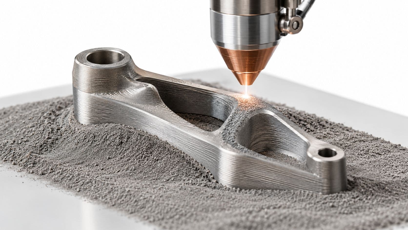
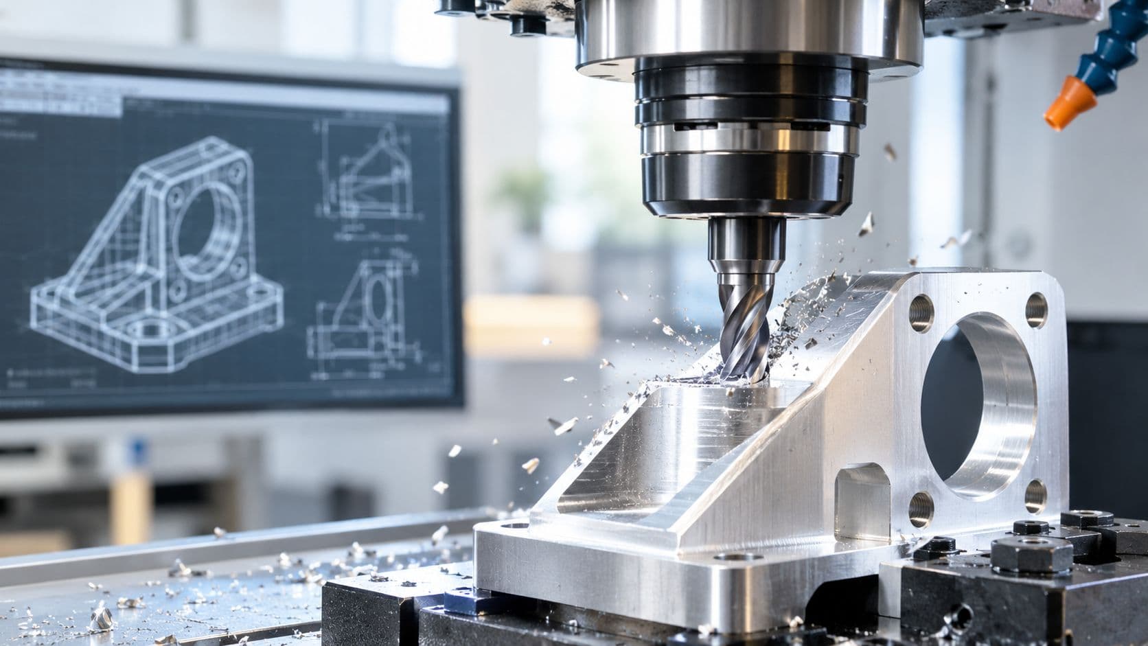
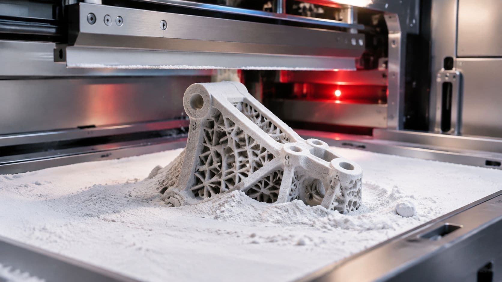
Prototype strategy gets messy when teams expect one method to answer every question. It won't. CNC machining can validate geometry and fit in real engineering plastic. SLA can reveal shape fast. Vacuum casting can approximate appearance and small-batch behavior. Rapid tooling can produce true molded resin parts. Each method answers a different set of risks.
Why one prototype process rarely answers every question
Use the process that best matches the decision you're making.
If you're checking board fit, connector access, or threaded insert locations, CNC machining is often a strong choice because it produces stable, accurate features in production-like plastics. If you need a visual model quickly, SLA may be enough. If your industrial design team wants several appearance samples with soft-touch or production-like finishes, vacuum casting can be very useful.
Rapid tooling sits in a different category. It becomes attractive when the team must test actual molded behavior, including gate influence, ejection, resin response, and batch consistency. That's why plastic injection molding parts often enter the conversation before mass production starts.
This process map helps frame those choices:

A practical workflow for early programs
A disciplined workflow usually looks more like staged filtering than a straight line.
- Start with form and interface learning. Use CNC, SLA, or another quick method to verify envelope, assembly access, and human interaction.
- Move to appearance or short-run replication when needed. Vacuum casting helps when stakeholders need several similar parts without full tool commitment.
- Use rapid aluminum tooling when molded behavior matters. This is the point where the team wants to learn from the actual molding process rather than from a substitute.
The overlooked issue is that low-volume molding should not be viewed as “mini mass production.” It has its own risks. New tools may need process tuning, part quality can drift early, and some small-batch economics are worse than expected.
That matters most for engineering teams making pilot decisions. If your goal is to test geometry only, molded parts may be more information than you need. If your goal is to validate assembly behavior in the intended resin and process, molded pilot parts may be exactly what you need.
The right partner helps you switch methods as the question changes, instead of forcing every question through one manufacturing process.
Analyzing Cost Drivers and Lead Times
Injection molding is famous for low unit cost, but that reputation can mislead small-batch programs. The trap is simple. Teams see the long-term economics of molding and assume the same logic applies to pilot runs. Often, it doesn't.
Why small batches surprise teams
The hidden cost stack in low-volume molding has several layers.
First comes tooling amortization. Even a fast-turn tool is still a dedicated manufacturing asset that has to be designed, built, adjusted, and maintained. Then comes cycle time, which affects machine occupancy and output. Material waste also matters, especially when sprues, runners, startup scrap, and rejected early parts are included. Secondary operations such as trimming, finishing, inserts, or assembly add more cost than many first-time buyers expect.
This cost picture is especially important for prototype quantities.

The low-volume trade-off becomes clearer with actual data. Rapid aluminum tooling can carry a 40% to 60% higher per-part cost than CNC machining for volumes under 500 because of secondary operations and material waste. In addition, 35% of low-volume runs fail initial quality checks due to mold settling. Those settling effects can require early cycles before dimensions stabilize, which is one reason quoted lead times and usable-part lead times aren't always the same thing.
Don't ask only, “How fast can the first shot happen?” Ask, “When will stable, acceptable parts be ready to ship?”
Where injection molding starts to make sense
There isn't one universal crossover point because geometry, material, finish, and inspection requirements vary. But there is a practical pattern.
- Very early validation: CNC or additive methods often win because they avoid tooling commitment.
- Appearance batches or presentation sets: Vacuum casting can bridge the gap well.
- Pilot molded parts: Rapid tooling makes sense when the project needs real resin behavior and repeated part geometry.
- Scaled production: Injection molding becomes increasingly attractive as volume rises and the tooling investment is spread across more parts.
The mistake is treating “under 1,000 pieces” as a single category. A few hundred cosmetic enclosures and a few hundred functional clips may have very different economics. One may tolerate hand finishing. The other may become expensive because each defect or secondary step consumes engineering time.
The best quoting conversations surface those details early. Ask what operations happen after molding, what dimensions are likely to drift during startup, and what quality criteria define a shippable batch.
Implementing Finishes Inspections and Quality Pathways
A molded part isn't done when it leaves the tool. Many products still need texture, paint, markings, plating, or assembly-ready inspection before they can move into production use.
Finishes need to support use, not just appearance
Surface finish decisions should start with function. A matte texture can hide handling marks and improve grip. A smoother surface may be easier to clean. Paint can unify appearance across components made by different processes. Laser marking or pad printing may be needed for identification, user instructions, or compliance details.
The key is to define finish intent in engineering terms, not just aesthetic language.
- Cosmetic expectation: Say whether the surface is show-face, hidden, or assembly-only.
- Functional requirement: Note if the finish must support grip, cleaning, chemical exposure, or marking durability.
- Measurable target: Use specified Ra or Rz targets when the surface roughness matters to function or mating behavior.
A finish that looks good on a sample can still create problems later. Paint thickness may affect fit. Texture can make ejector witness more visible. Decorative markings can shift if datums aren't controlled.
Inspection and documentation habits that prevent trouble
Inspection should match the risk of the feature.
A CMM works well for critical dimensions and datum relationships. Scan-based comparison helps with complex surfaces and global shape review. Go/no-go fixtures are useful when the question is simple and repeated, such as whether a snap feature seats or a tab clears a slot. Teams that need formal reports often combine these methods instead of relying on only one.
For a practical overview of measurement workflows, this guide to CMM inspection services is worth reviewing.
Quality pathways also depend on the market. General industrial programs often align to ISO 9001 practices. Automotive work may require IATF 16949 expectations. Medical device programs usually demand stronger traceability and document control under ISO 13485 workflows. The standards differ, but the daily habits are similar: revision control, material traceability, inspection records, nonconformance handling, and clear approval status for shipped parts.
A part isn't really “in control” until the team can prove what it is, what it's made from, and how it was accepted.
That mindset prevents a lot of painful audit conversations later.
Conclusion Partnering with FIRMFG
The hard part of injection molding isn't learning the vocabulary. It's managing the handoff from prototype freedom to production discipline. Material choice affects flow and durability. DFM choices affect shrink, sink, and ejection. Prototype method affects what you learn, and what you miss. Cost depends not only on quantity, but on timing, settling, finishing, and inspection strategy.
That's why many engineering teams benefit from working with one manufacturing partner across multiple stages instead of splitting CNC, vacuum casting, molding, finishing, and inspection across disconnected vendors. A single partner can carry CAD intent forward, flag DFM issues earlier, and reduce the back-and-forth that often delays pilot runs.
FIRMFG fits that model well. The company supports rapid prototyping, low-to-mid volume production, injection molding, vacuum casting, surface finishing, and dimensional inspection in one workflow. Its no-MOQ approach is especially useful when teams need to test low-volume molded parts without forcing an artificial production quantity. For regulated and demanding industries, the stated ISO 9001, ISO 13485, and IATF 16949 quality systems also matter because they support traceability and structured release processes.
If you're planning a molded part program, the practical next step is simple. Upload the CAD, ask for DFM feedback before tooling, define what your pilot run must prove, and align material, finish, and inspection requirements before the first mold is cut.
If you need a partner that can take your project from CNC prototype to rapid tooling to certified low-volume production, FIRMFG is a strong place to start. Their team supports CAD upload, DFM review, molding, finishing, and inspection in one workflow, which helps engineering teams move faster with fewer handoff errors.