A complete guide to CNC machining for engineers and product designers. Learn about processes, materials, tolerances, DFM, and how to select a reliable supplier.
You've finished a CAD model. It looks clean on screen. The mounting holes line up, the wall thickness seems right, and the assembly mates perfectly in the software. Then the question lands: how do you turn that digital model into a physical part that's accurate enough to test, assemble, and trust?
That's where CNC machining earns its place. It's the process many engineers rely on when a part has to come out of solid material with controlled dimensions, predictable geometry, and repeatable results. It isn't a niche shop-floor trick. It's a core manufacturing technology used across serious product development and production. The global computer numerical control machines market was valued at USD 66.74 billion in 2022 and is projected to reach USD 132.93 billion by 2030, with a 10.3% CAGR from 2023 to 2030, while Asia Pacific held 34.6% of global revenue in 2022, according to Grand View Research on the CNC machines market.
For a new product designer, CNC machining can feel deceptively simple at first. You send a file, a machine cuts metal or plastic, and a box shows up. But most confusion starts in the space between those steps. Why is one bracket cheap and another expensive when both are small? Why can one shop hold a tight bore position and another asks to loosen the tolerance? Why does a part with only a few minutes of cutting time still come back with a meaningful quote?
Those questions matter even more when you're working on prototypes and low-volume builds, where speed and iteration often matter more than squeezing every second out of machine cycle time. If you're also comparing overseas and domestic sourcing, it helps to understand how rapid prototyping in this region fits into the wider picture of lead time, process capability, and communication.
Table of Contents
- What the acronym really means
- Milling as controlled carving
- Turning as rotational shaping
- How engineers choose a material
- What surface finish really means
- Tolerance is a design decision
- How shops prove a part is correct
- Small design choices change machining difficulty
- Why short machining time doesn't always mean low cost
- A better way to read a CNC quote
- What to ask before you place an order
- What good communication looks like
Introduction From Digital File to Physical Part
A CNC-machined part starts as geometry on a screen, but the machine doesn't understand design intent the way you do. It doesn't know which face is cosmetic, which bore locates a bearing, or which tolerance matters because another part has to slide into place. It only knows the instructions it's given, the tools loaded into it, and the physical limits of cutting real material.
That's why CNC machining is best understood as a chain of translated intent. Your CAD file defines shape. Manufacturing planning turns that shape into toolpaths. The machine follows those toolpaths to remove material. Inspection checks whether the result matches the drawing. If any link in that chain is weak, the final part can drift away from what you meant, even if the model itself was perfect.
For a designer, that shift in mindset is useful. Don't think of CNC as “printing a metal part.” Think of it as controlled subtraction from a block or bar of stock. Every pocket, corner radius, drilled hole, and surface has to be reached by a real cutting tool with a real diameter and a real path.
CNC machining works best when design intent is explicit. The less a machinist has to guess, the fewer problems show up in the first article.
The practical payoff is big. When the process is matched to the design, CNC parts can move quickly from prototype to bridge production without changing the whole manufacturing logic. A bracket you machine for testing may later stay machined for low-volume supply, or it may become the dimensional reference for a casting, molding, or forged part.
That's why engineers keep coming back to CNC machining. It sits at the intersection of speed, accuracy, and material realism. You're not holding a visual model. You're holding the actual metal or plastic your product may use, with real threads, real surfaces, and real fit conditions. For design validation, assembly checks, and functional testing, that makes all the difference.
The Core Concepts of CNC Machining
What the acronym really means
CNC stands for Computer Numerical Control. In plain language, that means a machine tool moves according to digital instructions instead of being guided by hand. If manual machining is like steering a car yourself, CNC machining is closer to giving a very disciplined robot a route, speed plan, and exact list of movements.
The basic idea has been around for a long time. The origin of modern CNC technology dates to 1952, when MIT and the U.S. Air Force created the first working numerically controlled machine. By 1972, computer-based control had largely replaced older punched-tape NC systems, according to this history of CNC development. That matters because today's multi-axis machines didn't appear out of nowhere. They grew from decades of refining how software controls motion.

A useful analogy is this: a CNC machine is a robotic sculptor, but one that's extremely literal. It won't improvise. It won't “clean up” your intent unless a programmer or machinist builds that thinking into the process. If the code says move here, cut there, retract, rotate, and finish this wall, that's exactly what it does.
The three-part workflow
Most confusion disappears once you separate CNC machining into three connected pieces:
- CAD model
This is the design definition. It gives the nominal geometry: lengths, diameters, surfaces, hole locations, and feature relationships.
- CAM software
CAM turns geometry into strategy. It decides how to rough, finish, drill, contour, and step through the job with specific tools and motion paths.
- CNC machine
The machine executes those instructions in the physical world, with motors, spindles, fixtures, cutting tools, coolant, and part zero locations.
A new designer often assumes the CAD file contains enough information by itself. It doesn't. A model says what the part should be. CAM decides how to get there. That's a big distinction.
**Practical rule:** If a feature looks easy in CAD but hard to reach with a round cutting tool, it isn't easy to machine.
This is also where CNC differs from 3D printing. Printing adds material layer by layer. CNC removes material from stock. That subtractive approach usually gives stronger material continuity and excellent dimensional control, but it also means every feature has to be accessible to the tool.
Once you grasp that, a lot of design advice starts to make sense. Internal corners can't be perfectly sharp with a round end mill. Deep, narrow cavities become difficult because tools deflect. Undercuts need special tooling or a different process. None of that is arbitrary. It comes from the physical reality of how chips are made and removed.
Key CNC Processes Milling Turning and Beyond
The two main processes most designers deal with are milling and turning. If you know which one fits your part shape, you'll make better design choices and ask better questions during quoting.
For a deeper look at feature types and machine behavior, this overview of what CNC milling is is a useful companion.

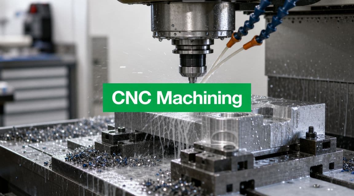
Milling as controlled carving
In CNC milling, the cutting tool rotates and removes material from a workpiece that's typically clamped in place. It operates similarly to carving a wood block with a spinning cutter, yet the machine controls every move precisely.
Milling is the go-to choice for parts with:
- Flat faces
- Pockets and cavities
- Slots
- Complex outer profiles
- Hole patterns
- Mixed geometry on multiple sides
A basic 3-axis mill moves in X, Y, and Z. That covers a huge amount of real work. You can machine the top of a block, cut pockets, drill holes, and contour surfaces accessible from one direction.
A 4-axis machine adds rotation around one axis. That helps when the part needs features around its sides without repeated manual re-fixturing.
A 5-axis machine adds even more freedom by allowing the tool or part to tilt and rotate. The easiest mental model is to picture painting a sculpture. A 3-axis setup lets you approach from limited directions. A 5-axis setup lets you angle the brush to reach complex surfaces more naturally. For impellers, organic housings, angled ports, and compound surfaces, that can reduce setups and improve access.
Machine behavior during milling depends heavily on feeds, speeds, and chip load. High-end milling spindles can reach 60,000 RPM, and adaptive control can automatically adjust cutting speed in response to material resistance, as described in this CNC machining guide. That's why one machine can rough aggressively and then shift into a fine finishing pass through programming and process control rather than a complete hardware change.
A quick video can help make that movement more intuitive:
Turning as rotational shaping
In CNC turning, the workpiece spins and the cutting tool moves against it. The analogy here is a potter's wheel, except instead of shaping soft clay by hand, the machine cuts a rotating bar or blank with a rigid tool.
Turning is ideal for:
- Shafts
- Bushings
- Pins
- Threaded cylinders
- Cones
- Grooved round parts
If the part is mostly rotationally symmetric, turning is often the efficient starting point. You can make diameters, shoulders, grooves, chamfers, and threads quickly because the spinning workpiece naturally defines the round geometry.
Modern lathes can also include live tooling and sub-spindles, which lets them do more than simple round work. But the core decision still holds: if your part has a round geometry, start by asking whether it belongs on a lathe.
A quick process comparison
| Attribute | CNC Milling | CNC Turning |
|---|---|---|
| Primary motion | Rotating tool cuts a fixed workpiece | Rotating workpiece cuts against a tool |
| Best for | Blocks, plates, prismatic parts, multi-face geometry | Cylindrical or rotational parts |
| Typical features | Pockets, slots, flat surfaces, contours | Diameters, tapers, grooves, threads |
| Setup logic | Often driven by feature access from multiple sides | Often driven by chucking and part length |
| Designer shortcut | Use when shape looks carved from a block | Use when shape looks made from a spinning bar |
If you can sketch the part as a profile and imagine spinning it around a centerline, turning may be the natural process.
Where EDM fits
Some parts don't fit cleanly into standard milling or turning. That's where processes like EDM can help. Electrical Discharge Machining removes material using controlled electrical discharges instead of a conventional cutting tool.
Designers usually encounter EDM when a feature is:
- very difficult to reach with a rotating cutter,
- extremely sharp or fine in geometry,
- or made from a hard conductive material where conventional access is a problem.
You don't need to memorize every specialty process. The key is to recognize when a design is asking a standard cutter to do something unnatural. That's often the signal to ask whether a different process would make the part more practical.
Choosing Materials and Surface Finishes
Material choice changes everything. It affects strength, weight, corrosion behavior, machining difficulty, cosmetic appearance, and cost. Surface finish then changes how the part feels, looks, and sometimes performs in service.

How engineers choose a material
A practical way to choose is to start with function, not habit. Don't pick aluminum because it's common. Pick it if its properties match what the part has to do.
For CNC-machined prototypes, designers often sort materials into two broad groups.
Metals are the usual choice when you need stiffness, structural strength, heat resistance, wear resistance, or threaded durability. Aluminum is popular for general-purpose housings and brackets because it machines well and keeps weight down. Stainless steel makes sense when corrosion resistance matters. Titanium comes up when weight, strength, and demanding service conditions all matter at once, though it's typically more challenging to machine.
Plastics work well when weight, electrical insulation, chemical resistance, or low friction matter more than raw strength. ABS is common in prototype work. Acetal, often called Delrin, is widely used for low-friction and dimensionally stable components. PEEK appears when the application is more demanding and the environment pushes beyond what commodity plastics can handle.
A useful design habit is to ask four questions:
- What load does the part carry
- What environment will it live in
- Does appearance matter
- Does the prototype need to match final production material
If the part is for fit checking only, you may not need the final material. If it's for a functional test, substituting too freely can mislead you.
What surface finish really means
Surface finish is where many drawings become vague. A designer may say “smooth,” but that could mean very different things to machining, inspection, and the customer handling the part.
In shop language, surface finish often starts with the as-machined condition. That means the tool marks from the cutting process remain visible. Depending on the toolpath and cutter, that may be perfectly acceptable for a hidden mounting face and completely wrong for a visible consumer-facing surface.
Common finish choices include:
- As-machined for functional prototypes and hidden features
- Bead blasted for a more uniform matte appearance
- Anodized when aluminum needs a protective and often cosmetic surface layer
- Polished or refined cosmetic surfaces when appearance is part of the requirement
A finish callout should connect to purpose. Cosmetic faces, sealing faces, sliding surfaces, and hidden internal faces rarely need the same treatment.
The most expensive finish isn't automatically the right one. If only one face is customer-visible, specify that face clearly. If a bore is used for bearing fit, care more about dimensional control and functional finish than about the color or texture of the outside.
Good CNC design separates functional surfaces from cosmetic surfaces. Once you do that, finish decisions become easier and quotes become clearer.
Achieving Precision Tolerances and Quality Control
Tolerance is a design decision
A dimension without tolerance is incomplete, but overusing tight tolerances is one of the fastest ways to make a part expensive and harder to produce consistently.
Think of tolerance like parking space width. If you're parking a bicycle, the space can be small and you still succeed easily. If you're parking a truck, the margin matters a lot more. In machining, a loose tolerance gives the process more room to succeed. A tight tolerance leaves less room for variation, so the machine setup, tooling, workholding, and inspection all have to be more disciplined.
CNC machining can achieve micron-level precision, with repeatability down to ±0.0001 inches in controlled environments, according to this CNC machining precision overview. The same source also notes that mathe regionbility improves when designers use the largest practical tool diameter, add large internal fillets, and limit cavity depth to about 4× cavity width. Those rules aren't cosmetic. They reduce tool deflection and help the machine hold size more reliably.
A common beginner mistake is applying a tight tolerance to every dimension on the drawing because it feels safer. It usually isn't. It can force unnecessary finishing passes, extra inspection, and more process risk.
How shops prove a part is correct
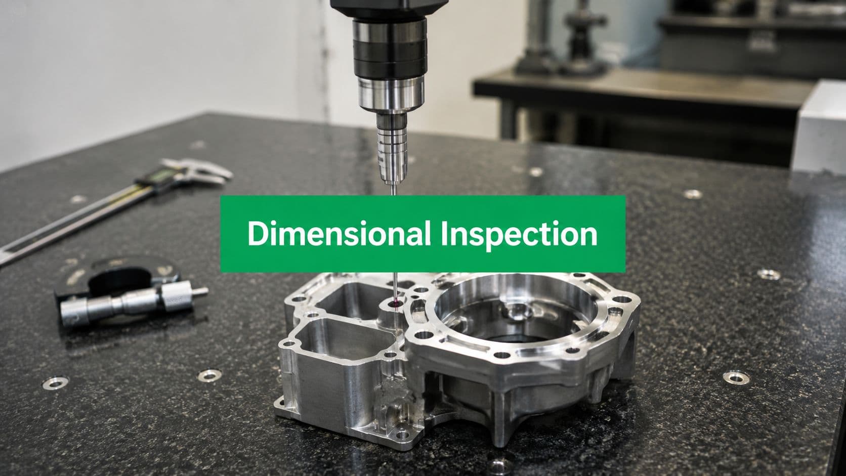
Precision isn't just about what the machine can do. It's about what the shop can verify.
A CMM, or coordinate measuring machine, is one of the most common tools used for that job. The simplest way to picture it is as a highly precise automated probe that touches selected points on a finished part and compares those measurements to the nominal CAD or drawing definition. Instead of trusting that the machine probably cut the right geometry, the shop checks actual physical points.
A shop may also use laser scanning or other inspection methods depending on the geometry and tolerance needs. For detailed incoming validation, many teams also ask for first article inspection when they want documented confirmation that the first manufactured part matches the drawing before more units are made.
Here's what a strong quality approach usually includes:
- Defined datums so everyone measures the part from the same references
- Inspection planning focused on critical features, not random dimensions
- Verified offsets and setups before full production starts
- Documented results when the part has assembly, compliance, or customer quality implications
Tight tolerance parts fail quietly when datums are unclear. The machine may cut exactly what the setup implied, not what the designer intended.
That's why good drawings matter. If you want a hole pattern located relative to a bearing bore, define that relationship clearly. Inspection can only confirm what the drawing specifies.
Design for Manufacturing and Understanding Cost
A lot of designers still assume CNC cost mostly comes from how long the cutter is engaged with the part. That's only part of the picture. In prototype and low-volume work, the hidden costs often matter more.

Small design choices change machining difficulty
The easiest way to reduce cost is to make the part easier to machine without hurting function.
Here are several DFM habits that pay off quickly:
- Use larger internal radii when possible. Small corner radii often force small tools, and small tools cut slower and deflect more easily.
- Avoid very deep narrow pockets unless the function strictly requires them. They limit tool choice and create chatter risk.
- Use standard holes and threads where you can. Custom feature sizes can trigger extra tooling steps.
- Keep walls reasonably sturdy if the part doesn't need to be ultra-thin. Thin walls can vibrate or distort during cutting.
- Apply tight tolerances selectively only to features that directly control fit or performance.
- Consolidate setups by designing features that can be reached logically from fewer orientations.
Some suppliers, including LC Proto, start jobs with a DFM review to flag issues such as difficult tool access, unrealistic tolerances, or features likely to drive extra setup and inspection work. That kind of feedback is often more valuable than a fast quote with no questions asked.
Why short machining time doesn't always mean low cost
For prototype and low-volume work, the true cost of a CNC part is dominated by setup time, programming, and tooling, not just machine runtime, as discussed in this CNC shop cost breakdown video. Buyers often miss those hidden costs, especially when they compare quotes only by how long the machine appears to be cutting.
This catches people off guard because the finished part can look simple. But behind that part, the shop may have to:
- choose stock size and cutting method,
- build or select workholding,
- program toolpaths in CAM,
- load and measure tools,
- set work offsets,
- run a first piece carefully,
- inspect critical features,
- and sometimes repeat the process on another side or another machine.
If you order one part or a small batch, those preparation costs don't get spread over many units. That's why a prototype bracket can cost more than expected even when the cutter only spends a short time in material.
The first part pays for decisions. Later parts benefit from them.
Repeated setups also matter. A part that needs to be flipped several times, indicated in carefully, and probed again can cost far more than a part with similar volume but smarter feature access. Scheduling affects this too. If a shop has to interrupt work, change tooling, or run a one-off part outside an efficient workflow, cost rises even when the geometry hasn't changed.
A better way to read a CNC quote
When you review a quote, don't ask only, “How fast can this be cut?” Ask questions like:
- How many setups does this part require
- Are any features forcing special tooling
- Which tolerances are driving the inspection plan
- Could a radius, pocket depth, or hole spec be adjusted
- Is the chosen material creating avoidable machining difficulty
A good quote review often leads to small drawing changes that keep the part functionally identical while making it easier and cheaper to build.
If you remember one idea from this whole guide, make it this one: good DFM reduces cost before the spindle starts turning.
How to Select the Right CNC Machining Partner
The right supplier isn't just the one with the lowest number on the quote. It's the one that can make your specific part correctly, communicate clearly, and reduce risk before problems reach your bench or your assembly line.
What to ask before you place an order
Start with capability fit. If your part has compound surfaces and multiple angled features, ask whether the shop regularly handles that kind of geometry. If your drawing includes critical bores, threads, or cosmetic faces, ask how they fixture, inspect, and protect those features.
A practical checklist looks like this:
- Process fit
Can they support the actual process your part needs, whether that's 3-axis milling, 5-axis machining, turning, or a combination?
- Material familiarity
Have they machined your chosen alloy or plastic in similar applications?
- Inspection capability
Can they verify the tolerances you care about with the right equipment and reporting method?
- DFM feedback quality
Do they question risky details, or do they accept the file and hope it works?
- Finishing coordination
Can they manage the surface finish and post-processing requirements without confusion?
What good communication looks like
Communication is usually the clearest signal of whether a supplier will feel like a partner or a black box.
Good shops do a few things consistently. They ask about datum strategy when tolerances are tight. They clarify whether dimensions are cosmetic or functional. They point out features that may need redesign before production. They don't hide uncertainty behind vague confidence.
You should also pay attention to how they talk about quality. A strong manufacturing partner can explain how they'll hold the part, how they'll inspect it, and where they see risk. That matters more than broad claims about precision with no manufacturing logic behind them.
The best supplier relationship feels collaborative. The drawing is still your authority, but the shop helps translate it into a dependable process. That's what you want when your project involves prototypes, engineering changes, and parts that have to work the first time they're assembled.