Master inspection planning for CNC prototypes & low-volume parts. Get our 2026 guide on a risk-based framework for objectives, tools, & documentation.
You've probably had this happen. A CNC prototype comes off the machine, the dimensions look clean, the inspection sheet shows green boxes, and the part still fights the assembly on the bench. The dowel pins need persuasion. The bearing feels tight in one orientation and loose in another. The mating face seals in CAD but not in your hands.
That's usually not a machining problem alone. It's an inspection planning problem.
For prototypes and low-volume runs, the hard part isn't measuring everything. It's deciding what must be measured, how it should be measured, when to check it, and what result proves the part is fit for use. A generic checklist won't do that. A bulletproof plan has to reflect the drawing, the function, the process risk, and the realities of the shop floor. It also has to work under prototype pressure, where lead time matters and nobody wants to turn first-article inspection into a paperwork exercise that delays learning.
Table of Contents
- Start with the real job of the part
- Scope by risk, not by drawing order
- Use the cheapest tool that can answer the question correctly
- Inspection Method Selection Guide
- Where advanced metrology earns its keep
- When 100 percent inspection is the right call
- How to use sampling without fooling yourself
- What the inspection record must contain
- How nonconformance should change the next plan
Why Most Inspection Plans Miss the Mark
Most bad inspection plans fail in a predictable way. They treat the drawing like a flat list of dimensions instead of a map of functional risk. The result is a report full of measurements that are technically correct but operationally weak.
A common example in CNC prototyping is a housing with a bore, a bolt pattern, and a mounting face. The report may confirm the bore diameter, hole size, and outside profile, yet the part still binds during assembly because no one checked the positional relationship between the bore and the mounting datum in the same measurement setup. The dimensions passed. The part failed.
That happens when inspection planning starts with, “What can we measure quickly?” instead of, “What would make this part fail in actual use?” ASQ's PDCA guidance is useful here because it frames the work correctly. An effective inspection-planning workflow starts by defining measurable pass/fail criteria, then documenting the exact procedure and executing it as a repeatable test, with small-cycle iteration built in through ASQ's PDCA cycle guidance.
**Practical rule:** If the plan doesn't tell two different inspectors how to reach the same judgment on the same feature, it isn't finished.
In a precision machine shop, the first article should be treated like a controlled experiment. You're not just verifying dimensions. You're proving whether the chosen datums, process sequence, workholding strategy, and measurement method are good enough for this part family.
What usually goes wrong
- Datum confusion: The machinist, CMM programmer, and design engineer aren't working from the same functional reference frame.
- Over-inspection of low-risk features: Time gets burned checking noncritical overall sizes while fit-driving geometry gets shallow review.
- Weak acceptance criteria: Surface condition, edge break, burr condition, or form requirements are implied but not clearly written.
- No feedback loop: A failure gets reworked, but the plan doesn't change, so the same issue appears on the next batch.
A passed report is not proof of a good part if the report never tested the failure mode that matters.
Prototype and low-volume work make this sharper, not easier. You don't have the volume to hide behind averages, and you often don't have mature process data yet. That's why inspection planning has to be deliberate from the start.
Defining Your Inspection Objectives and Scope
Inspection planning gets stronger the moment you separate inspection purpose from inspection activity. Before you pick a tool or create a check sheet, decide what the inspection must prove.

Start with the real job of the part
A prototype inspection plan for a one-off concept part isn't the same as a plan for a low-volume bridge run. In the first case, the plan often needs to answer fit, function, and design-learning questions. In the second, it has to establish repeatability and catch drift before several dozen parts are affected.
I usually divide objectives into a few practical buckets:
- Fit and assembly
Does the part locate, mate, clamp, seal, or rotate the way the product needs?
- Functional performance
Are the surfaces, bores, threads, and critical relationships capable of doing the job under real use?
- Cosmetic and handling quality
Are visible surfaces, edge conditions, and finish acceptable for the intended stage of the product?
- Process baseline
Are you trying to learn whether this routing, this fixture, and this machine strategy can support future repeat builds?
Those goals change the inspection plan materially. A cosmetic prototype for stakeholder review may need careful visual standards and less exhaustive geometric verification. A bearing carrier headed for a validation build needs the opposite.
Scope by risk, not by drawing order
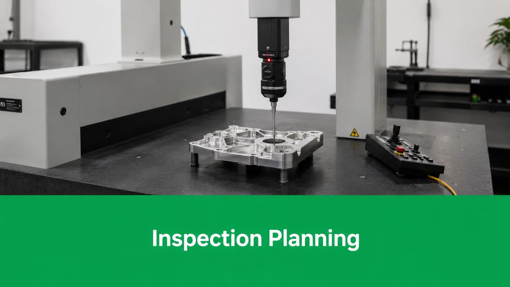
ScienceDirect describes an inspection plan as a customized strategy that prioritizes high-risk equipment and specifies tasks and frequencies, which is the right mindset for machined parts too. The useful takeaway is the risk-based part. Inspection planning works best when it focuses limited effort on the features most likely to cause failure, turning inspection from a generic checklist into a more data-driven control process, as summarized in ScienceDirect's overview of inspection plans.
Here's the practical translation for CNC work. Don't scope the plan by starting at the top-left of the drawing and marching down. Scope it by critical-to-quality features.
A good drawing review asks:
- Which dimensions control assembly?
- Which features establish datums for later operations?
- Which tolerances are tight because function demands them, not because someone copied an old title block?
- Which surfaces affect sealing, bearing fit, sensor alignment, or preload?
- Which geometric controls could fail even if every size dimension looks acceptable?
A simple before-and-after example makes the difference clear.
Weak scope: inspect all dimensions once, note material and finish, and sign off.
Risk-based scope: fully verify the bearing bore, bore-to-face relationship, hole pattern position relative to primary datum, thread depth on loaded fasteners, and sealing surface condition. Spot-check low-risk external profile dimensions unless they drive packaging.
If the print uses GD&T, many teams will either gain control or lose it. The drawing has to be read as a functional system, not as isolated callouts. If you need a refresher on datum structure and feature controls, this guide to geometric dimensioning and tolerancing is a useful reference point.
The best prototype inspection plans are selective, not exhaustive. They spend the most attention where failure would be expensive, hard to detect later, or misleading during design validation.
A scope that's too broad slows learning. A scope that's too narrow gives false confidence. The right balance comes from asking one blunt question for each feature: if this is wrong, what breaks next?
Choosing the Right Inspection Methods and Tools
The tool should match the question. That sounds obvious, but a lot of wasted time in prototype shops comes from using a high-end measurement method where a basic one would do, or worse, using a quick manual check for geometry that really needs a structured setup.
Use the cheapest tool that can answer the question correctly
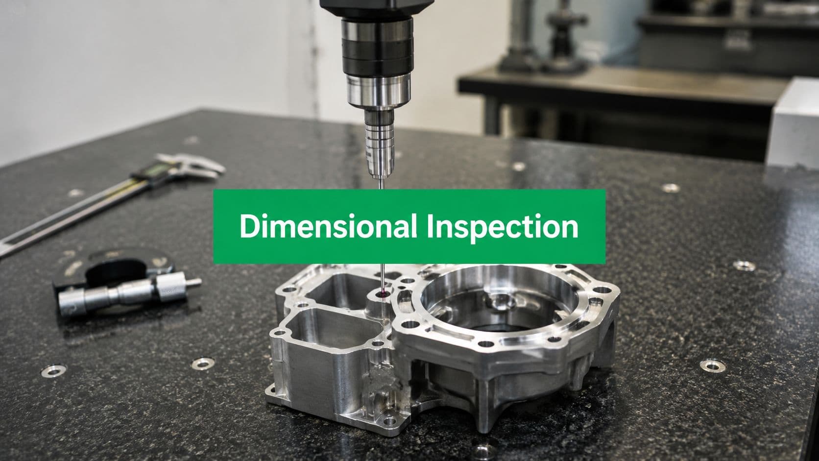
For low-risk external dimensions, a caliper may be enough. For a critical bore, use a bore gauge or an internal micrometer if the tolerance and access demand it. For a true position callout tied to a datum structure, move to a CMM if you want confidence instead of interpretation.
The same logic applies to visual and surface checks. A simple visual inspection under controlled lighting can catch burrs, chatter, denting, and edge condition issues early. That's fast and valuable in prototyping. It just shouldn't be mistaken for dimensional proof.
Three habits keep method selection honest:
- Match the setup to the tolerance. Don't use a coarse method and then argue over tenths in a meeting.
- Match the method to the geometry. Curved surfaces, compound angles, and GD&T relationships usually need more than hand tools.
- Match the output to the decision. If you need a pass/fail answer, one method may be enough. If you need deviation mapping for redesign, choose a method that produces that data.
Recent research on inspection planning for reconstruction-heavy inspections makes a point that also applies to shop metrology. Maximizing coverage alone can be counterproductive if the viewing geometry is poor, because measurement reliability depends on incidence angles and the specific inspection objective, not just how much of the surface was “seen,” as discussed in this research on planning for measurement quality and viewing geometry. In practice, that means a 3D scan is only useful when the scan strategy supports the features you care about.
Inspection Method Selection Guide
| Method | Best For | Typical Tolerance | Pros | Cons |
|---|---|---|---|---|
| Visual inspection | Burrs, scratches, coating issues, obvious damage | Qualitative | Fast, cheap, useful at receiving and in-process checks | Subjective if standards aren't defined |
| Calipers | Noncritical external dimensions, quick setup checks | Moderate shop tolerances | Fast, widely available, good for first-pass screening | Weak for tight bores, form, and GD&T relationships |
| Micrometers | Shaft diameters, thicknesses, tighter size control | Tighter size features | Better repeatability than calipers for size checks | Limited to accessible features, still not enough for geometry |
| Bore gauges | Internal diameters and bore consistency | Tight bore work | Good for fit-driving bores, better than guessing with telescoping tools | Requires operator skill and correct master setup |
| Height gauge and surface plate | Datum-based linear checks, hole locations in simple layouts | Moderate to tight, depending on setup | Strong for shop-floor verification with stable references | Can get slow on complex parts |
| Pin gauges and thread gauges | Hole size checks, go/no-go functional confirmation | Functional limits | Fast and simple for acceptance decisions | Doesn't give full dimensional picture |
| CMM | GD&T, positional relationships, datum-based geometry, complex parts | Tight tolerance and complex geometry | High confidence, structured reporting, repeatable | Programming time, fixturing, slower for very simple checks |
| 3D scanning | Freeform surfaces, profile comparison, cast or sculpted forms, fast deviation review | Goal-dependent | Rich visual feedback, useful for shape comparison and redesign input | Accuracy depends on setup, line of sight, surface condition, and scan strategy |
A formal first article inspection overview can help decide when the part needs full ballooned verification versus a more targeted low-volume control plan.
Where advanced metrology earns its keep
CMM inspection earns its time when the part has stacked relationships that can't be trusted through manual methods. Think valve bodies, optical mounts, precision brackets, and any part where hole pattern position relative to a bore or mounting face matters more than the raw dimensions alone.
3D scanning earns its keep in different situations. It's useful on sculpted surfaces, ergonomic forms, blended contours, or prototype parts where you want to compare actual shape to CAD and hand that feedback back to design quickly. It can also expose where machining strategy or tool deflection altered a profile in ways a few point measurements would miss.
Don't use a scanner just because the color map looks impressive. Use it when the part's geometry or the redesign loop benefits from dense surface information.
Whatever method you choose, data integrity still decides whether the plan is trustworthy. If the instrument isn't calibrated, the setup isn't stable, or the operator doesn't understand the reference scheme, the report may look polished while telling you very little.
Implementing Sampling Strategies and AQL
Prototype work usually starts with one default position. Inspect everything that matters.

That's the right instinct for a first article, and it's often still the right instinct for low-volume runs where every part may go into a customer build, an internal validation unit, or an expensive assembly. But small-batch production also forces a practical question. At what point does full inspection stop adding value and start consuming time that should go into process control?
When 100 percent inspection is the right call
Six Sigma guidance recommends reserving 100% inspection for critical characteristics while using random sampling for high-volume processes, with the sampling decision based on risk and process criticality. The same guidance also stresses that Measurement Systems Analysis must come before trusting the data, which is easy to overlook in a small shop when everyone is moving fast. That framework is summarized in this SPC and sampling guidance from 6Sigma.us.
For CNC prototypes and low-volume production, 100 percent inspection is usually justified when:
- The part is a first article.
- The feature is CTQ, such as a sealing diameter, bearing bore, precision datum face, or safety-related thread.
- The process is new, including a new fixture, new machine, new programmer, or new toolpath strategy.
- The consequence of escape is high, especially when failure appears only during assembly or test.
That doesn't mean every feature on every part gets the same level of scrutiny. It means every critical characteristic gets complete attention until the process has earned trust.
How to use sampling without fooling yourself
Once the part design is stable and the run size grows, a written sampling plan becomes useful. In low-volume manufacturing, I'd rather see a simple, disciplined plan than a fake “SPC program” that nobody maintains.
A practical approach looks like this:
- Keep CTQ features on full inspection
Don't negotiate away the features that drive function.
- Sample stable, lower-risk features
External dimensions, cosmetic features, or nonfunctional lengths can move to random checks once the process shows consistency.
- Define the lot clearly
A lot should represent parts made under comparable conditions, not a mixed pile from different setups or tooling states.
- Write the reaction plan
If the sample fails, what happens next? Additional sampling, full lot screening, rework review, or hold for engineering disposition.
AQL can help formalize that decision, but it's often misunderstood. In plain shop language, AQL is part of a lot acceptance rule. You inspect a defined sample from a lot, compare defects against the acceptance criteria, and then decide whether the lot moves forward or needs containment. The value of AQL isn't the acronym. The value is that it forces you to write down the rule before the parts are in front of you.
If you're trying to connect that to process maturity, a quick review of process capability index concepts helps separate stable process thinking from one-time inspection effort.
Sampling is only efficient when the process is stable enough that the sample tells the truth about the lot.
For prototypes, many teams jump to sampling too early because full inspection feels slow. Usually the core issue isn't inspection volume. It's that the plan hasn't yet separated critical features from low-risk ones, so every dimension is being treated like a crisis.
Documenting the Plan and Managing Results
A solid inspection plan becomes real when someone can execute it without asking five clarifying questions at the bench. That means the document has to do more than list dimensions. It has to tie the drawing, the method, the acceptance criteria, and the disposition path together.
A good first-article packet for a CNC part is usually easier to use when it's boring. Clean layout. Ballooned drawing. Clear feature IDs. No mystery abbreviations.

What the inspection record must contain
For a precision machined component, the inspection record should capture at least these fields:
- Feature ID: tied directly to the ballooned drawing
- Requirement: nominal dimension, tolerance, GD&T control, finish note, or visual requirement
- Datum reference or setup reference: especially important for geometric checks
- Inspection method: caliper, micrometer, bore gauge, CMM, scanner, gauge pin, visual standard
- Actual result: measured value or qualitative judgment against a defined standard
- Pass or fail decision: unambiguous, not implied
- Inspector and date: traceability matters, even in prototype work
- Disposition notes: if something misses, the next action is recorded immediately
A running example helps. Say you're inspecting a machined aluminum manifold body. The bore size is in spec, but a port-face flatness issue causes sealing trouble in assembly. If the plan only captured overall dimensions and thread checks, the actual failure mode would be invisible in the paperwork. If the plan required the sealing face to be checked with the correct method and acceptance rule, the issue would be caught before test build.
That's where in-process quality control earns money. If a critical face is prone to movement after roughing, don't wait for final inspection to discover it. Insert an in-process check after the operation that creates the risk. Final inspection should confirm. It shouldn't be the first moment of truth.
The cheapest defect is the one caught before the next operation hides it.
Teams that want a visual walkthrough of how structured inspection records support manufacturing control may find this useful:
How nonconformance should change the next plan
A lot of shops handle nonconformance too narrowly. They focus on disposition only. Scrap it, rework it, or ask engineering for use-as-is approval. That's necessary, but it's not enough.
The better question is: what did this failure teach the plan?
Research on adaptive inspection makes the point that static preplanned routes often break down when conditions change, and modern inspection works better when global planning is combined with local adaptation, as outlined in this research on adaptive inspection under changing conditions. The same lesson applies to CNC manufacturing. If nonconformance reports keep pointing to the same issue, the inspection plan shouldn't stay frozen.
For prototype and low-volume work, that usually means one of these changes:
- Move a check earlier because waiting until final inspection costs too much.
- Tighten the method because the original tool wasn't resolving the underlying problem.
- Clarify the criterion because inspectors were interpreting a visual or geometric requirement differently.
- Split one feature into two checks when size alone wasn't enough and location or form also mattered.
A simple MRB process helps close the loop. When a part fails, the team should document the defect, containment action, root cause if known, and final disposition. Then the inspection plan should be revised if the failure exposed a blind spot. In prototyping, this revision cycle is not bureaucracy. It's how the process gets smarter between build one and build two.
Conclusion From Plan to Partnership
A strong inspection plan for a CNC prototype does five things well. It defines what success looks like. It scopes effort around risk instead of checking every feature equally. It uses the right tool for the measurement question. It applies full inspection and sampling deliberately. It turns results into usable feedback instead of static paperwork.
That matters more in prototyping and low-volume production than in mature high-volume work. You're often validating design intent and manufacturing method at the same time. A missed relationship, a weak datum strategy, or a vague pass/fail rule can send the team in the wrong direction fast.
The best inspection planning doesn't feel like administrative overhead. It feels like technical clarity. Everyone knows which features matter most, how they'll be checked, what counts as acceptable, and what happens if the part fails. That shared understanding saves time, reduces argument, and makes iteration more useful.
It also changes the relationship between designer and manufacturer. A good plan becomes a working agreement about what “good” means for this part, in this application, at this stage of development. That's where inspection stops being a final gate and starts becoming part of product development itself.
If you're reviewing a new CNC part right now, don't ask only whether the drawing is complete. Ask whether the inspection plan proves the part will work.