Understand what is design for manufacturing, its key principles, and practical application for CNC & injection molding. Essential guide for engineers in 2026.
The design review is done. The CAD looks clean, the renderings look impressive, and everyone thinks the project is ready for quotes. Then the manufacturing feedback comes back.
A pocket is too deep for the cutter you assumed would reach it. The molded housing has vertical walls with no draft. A bent bracket can't be formed in the sequence shown in the model. The printed prototype looked fine, but the production version now needs support removal in places nobody can reach. Suddenly the product isn't “almost ready.” It's back in revision.
That moment is where many teams first ask what is Design for Manufacturing, usually after losing time they thought they had. The frustrating part is that nothing was necessarily wrong with the design intent. The part may have done its job mechanically. It just wasn't designed with the factory, the tooling, or the assembly bench in mind.
Most delays like this don't come from one dramatic mistake. They come from a stack of small assumptions. A sharp internal corner in CAD becomes a specialty tool. A custom fastener becomes a sourcing headache. A tolerance that looked harmless on a drawing turns into extra inspection, extra setups, or scrap.
Design for Manufacturing, or DFM, is the discipline that prevents those surprises earlier. It closes the gap between a design that exists on screen and a design that can be made repeatedly, economically, and with predictable quality. If you're staring at a new product right now and wondering whether your design is production-ready, that's exactly the right time to think about DFM.
Table of Contents
- Designing with the factory in the room
- What DFM changes in practice
- Simplify what the factory has to do
- Standardize where function allows it
- Design assembly into the part, not after it
- DFM considerations by manufacturing process
- What a useful DFM review should cover
- A working checklist for your next design
Introduction The Moment Every Designer Dreads
A startup team once sent out a housing for quotation after weeks of industrial design refinement. The exterior looked production-ready. The internal features were dense but elegant. On screen, it felt solved.
The problem showed up when the part met real process constraints. The internal ribs created molding risk, several walls needed draft that would affect fit, and the snap features worked in theory but were awkward for tool design and assembly. The team hadn't designed a bad product. They had designed a product in isolation from how it would be made.
That's a common failure mode. Mechanical designers often work under pressure to hit packaging, strength, weight, and appearance targets. Manufacturing engineers inherit the geometry later and have to translate that intent into tooling paths, bend sequences, mold actions, fixtures, inspection plans, and repeatable output. If those conversations happen late, redesign is almost guaranteed.
Good DFM work feels boring at the right moment so production doesn't become exciting at the wrong moment.
The reason this hurts so much is that the cost is never limited to the revised model. Tooling may need to change. Lead times shift. Supplier confidence drops. Testing gets delayed because production-equivalent parts arrive later than planned. The schedule damage spreads outward.
That's why DFM matters. It isn't paperwork, and it isn't a factory saying no. It's a design method that asks a simple question early enough to help. Can this part be made well, at the target cost, with the target process, by real people using real machines?
Once you treat that question as part of design instead of a downstream check, product development gets smoother. Not easy, but far more predictable.
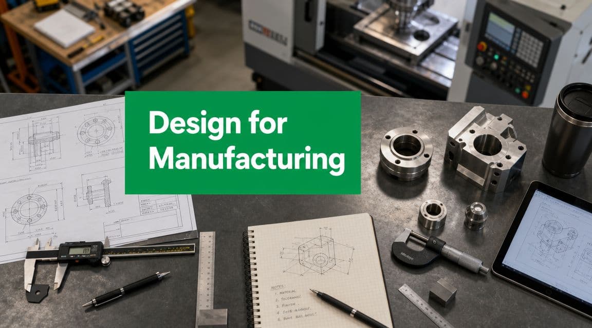
What Is Design for Manufacturing Fundamentally
DFM starts at the point where a design stops being only geometry on a screen and becomes a plan for real machines, real operators, and real variation. The question is simple: can this part be made repeatedly, at the target cost and quality, with the process you intend to use?
That sounds obvious, but it changes how a designer works. A clean CAD model can still be a poor production part if it requires special tooling, unstable setups, awkward inspection, or handwork nobody budgeted for. I've seen parts that looked elegant in the model and turned into expensive problems the moment someone had to machine them, mold them, or fixture them.
Designing with the factory in the room
A recipe is a useful comparison here. You write differently for a home kitchen than for a commercial bakery because the tools, repeatability, and throughput are different. Product design works the same way. A part built for CNC machining follows one set of practical rules. The same part built for injection molding, sheet metal, or additive manufacturing follows another.
That process-specific view is where DFM gets real. High-level advice like "simplify the design" is fine, but it does not help much when the actual question is whether a pocket is too deep for a standard end mill, whether a molded wall will sink, whether a bend flange leaves room for the brake tooling, or whether a printed overhang will need support and post-processing.
A CAD model is an instruction set for downstream work. Machinists read it as tool access and setup count. Mold designers read it as parting lines, draft, steel conditions, and ejection. Sheet metal shops read it as bend sequence, grain direction, and tool clearance. Inspection reads it as datum strategy and measurement access.

Good DFM means the design accounts for those readings early, while changes are still cheap.
What DFM changes in practice
DFM is often described as a cost-reduction method, but that description is too narrow. It is a way to make design decisions with production consequences in view. Cost matters. So do lead time, yield, assembly effort, cosmetic consistency, tooling complexity, and how much process variation the part can tolerate before it falls out of spec.
That is why DFM is rarely about chasing the "best" geometry in isolation. It is about choosing geometry that protects the function without making production fragile. A sharp internal corner may look harmless in CAD. In CNC machining, it can force a smaller tool, longer cycle time, and poorer rigidity. A perfectly vertical wall may satisfy the shape you want. In injection molding, it can turn into drag marks or ejection trouble if draft is missing.
This is also why DFM cannot be one generic checklist. The right answer depends on the manufacturing method. Design choices that help one process can hurt another. Thin walls may be attractive for molded parts when done correctly, but they can create chatter or distortion in machining. Complex internal channels may be easy to print and nearly impossible to machine in one piece.
**Practical rule:** If a feature only works when the supplier uses special handling, custom tooling, or heroic operator skill, the design is carrying hidden production risk.
DFM means designing the part and choosing the process together. The part shape, tolerances, material, finish, and assembly intent should fit the manufacturing route from the beginning. That is the difference between a model that merely looks finished and a design that is ready to survive production.
Key Principles That Drive Successful DFM
The core ideas behind DFM are straightforward. The hard part is applying them without weakening the product's function. Most successful DFM work comes from managing trade-offs, not chasing purity.
Simplify what the factory has to do
A reliable benchmark in DFM is to reduce part count and manufacturing operations early, because every added part or secondary operation increases touch time, fixture complexity, and defect opportunities, as noted in Xometry's practical DFM guidance.
That sentence is worth understanding precisely. Every extra thing the factory has to do creates another place for cost or variation to enter.
Consider a bracket assembly made from three machined blocks, fasteners, and a secondary alignment step. If the loads and packaging allow it, that same function may be delivered by one bent sheet metal part with captive hardware. The redesign doesn't just save material. It removes machining setups, loose components, and assembly error points.
A few common “before and after” patterns show up repeatedly:
- Before DFM: A housing with decorative internal pockets, stepped wall thickness, and multiple cosmetic details no user will ever see.
After DFM: Internal faces simplified to support the chosen process, while visible exterior surfaces keep the design language.
- Before DFM: Separate spacers, washers, and standoffs inserted during assembly.
After DFM: Stand-off geometry integrated into the primary part where the process can produce it reliably.
- Before DFM: Tight corner radii and deep, narrow pockets in a machined part.
After DFM: Radii aligned with standard cutting tools and pocket depths that don't force awkward reach conditions.
Standardize where function allows it
Standardization sounds unglamorous, but it prevents a lot of pain. Standard fasteners, common stock thicknesses, and familiar materials reduce procurement friction and lower the odds that one hard-to-source item holds up a build.
This applies to dimensions too. If every hole is slightly different because each was modeled around a local condition, the process becomes fragile. Standardized feature families are easier to machine, inspect, and assemble.
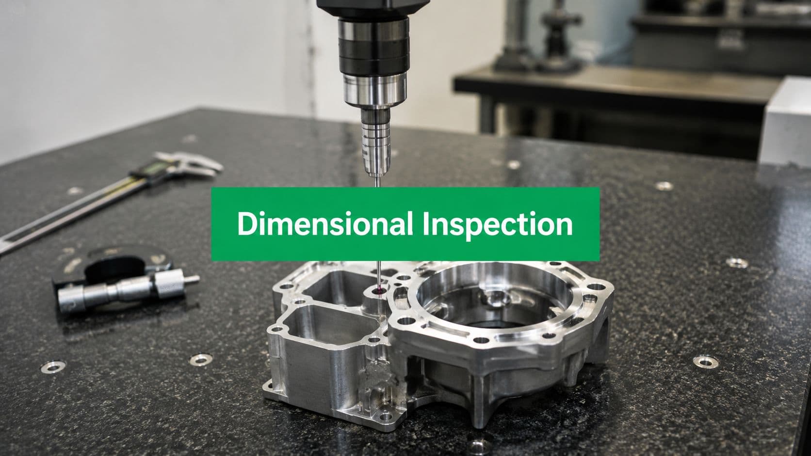
When tolerances are involved, discipline matters even more. If you want a useful refresher on how functional requirements should drive tolerance strategy, this guide to geometric dimensioning and tolerancing basics is worth reviewing before you lock your drawings.
Design assembly into the part, not after it
Some products are easy to manufacture and miserable to assemble. That's not good DFM. A design that requires awkward orientation, hidden fasteners, or forceful insertion will create trouble even if each component is individually easy to make.
Useful questions at this stage include:
- Can the assembler tell orientation immediately? Symmetry is good for aesthetics. It can be bad for foolproof assembly.
- Can a tool reach the fastener cleanly? Clearance on the model doesn't always mean a driver can engage in production.
- Does the part locate itself? Tabs, bosses, and lead-ins often do more for consistency than heroic assembly skill.
If your design depends on a careful technician “making it work,” the design still needs work.
The aim isn't to remove every challenge. The aim is to remove avoidable ones. Good DFM means the factory spends its energy making the product, not compensating for preventable complexity.
DFM in Practice Guidelines for Key Manufacturing Processes
Many articles often remain too abstract. DFM changes with the process. A shape that's perfectly reasonable for a machined prototype can become expensive, unstable, or impossible when you switch to molding or formed metal. Manufacturability depends on the process, not just the product, as emphasized in PTC's discussion of process-specific DFM.
DFM considerations by manufacturing process
| Consideration | CNC Machining | Injection Molding | Sheet Metal | 3D Printing (FDM/SLA) |
|---|---|---|---|---|
| Geometry freedom | Good, but limited by tool access | Constrained by mold opening and tooling | Driven by bend rules and flat pattern logic | High, but support and orientation matter |
| Internal corners | Need radii that match tools | Usually not the main issue compared with draft and wall behavior | Cut features are easy, formed shapes need planning | Often easy to create, but may print poorly |
| Wall strategy | Avoid thin, unstable features | Keep walls uniform where possible | Respect practical bend and flange relationships | Avoid thin walls that warp or break |
| Tolerances | Strong process for precision, but cost rises with tighter specs | Depends on tooling and part geometry | Good for many functional parts, but not every detail | Often suitable for fit checks more than final precision |
| Volume fit | Strong for prototypes and low to moderate volume | Strong when volume justifies tooling | Strong for enclosures, brackets, panels | Strong for prototypes, fixtures, and complex low-volume parts |
| Main DFM risk | Designing shapes the cutter can't reach efficiently | Ignoring draft, wall behavior, and mold action | Ignoring bend sequence and tool access | Treating printed geometry as if it were process-free |
CNC machining
CNC is forgiving compared with many processes, but it isn't magic. A machinist still needs tool access, workholding, and sensible feature relationships. If you want a practical process overview, this primer on CNC machining fundamentals is a useful companion.
The biggest mistake in CNC DFM is designing as if the cutter were infinitely small and infinitely rigid. It isn't.
Good CNC habits include:
- Use internal radii intentionally: Sharp internal corners force tiny tools, longer cycle times, and greater chatter risk.
- Keep pocket depth realistic: Deep pockets with small corner radii are a classic cost trap because the tool has to reach farther while staying stable.
- Think about setups: A part that needs to be flipped repeatedly or indicated from awkward faces often costs more than its geometry suggests.
- Apply tight tolerances selectively: Critical datums and fits deserve attention. Decorative or non-critical faces usually don't.
A clean mental model is this. CNC removes material with a rotating tool that needs access and stiffness. If your design ignores either, price and risk climb.
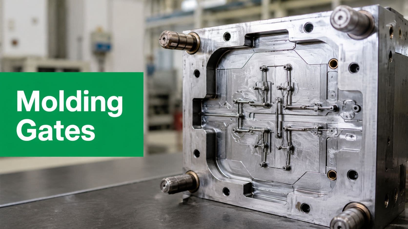
Injection molding
Molding punishes late corrections more than many other processes because tooling commits the geometry. If draft, wall behavior, parting line logic, and ejection weren't considered early, redesign gets expensive fast.
Three molding rules solve a surprising number of problems:
- Give vertical faces draft: Straight walls may look neat in CAD, but molded parts need release.
- Aim for consistent wall behavior: Large wall transitions can create cosmetic and dimensional issues.
- Avoid undercuts unless they are justified: Side actions and complex tooling can be appropriate, but they should earn their keep.
A common trap is designing a plastic part like a machined one. Machined features can often tolerate abrupt section changes and locally “perfect” geometry. Molded parts prefer flow-friendly, release-friendly, repeatable forms.
Plastic part design isn't just shape design. It's tool design by proxy.
Snap fits, bosses, and ribs can reduce assembly complexity in molded products, but only when they work with tooling and wall strategy rather than against them.
Sheet metal
Sheet metal rewards designers who think in flat patterns and bend sequences rather than solid bodies. Many beginners model the final shape first and assume the shop will “figure out” the bends. That's how you get collisions, inaccessible flanges, or dimensions that drift because the bend plan wasn't part of the design logic.
Strong sheet metal DFM usually means:
- Keep bends simple and consistent where possible
- Respect bend relief and flange relationships
- Place holes and cutouts with bending in mind
- Reduce welded assemblies when one formed part can do the job
For example, a box-like bracket built from separate plates may seem straightforward in CAD. In production, one properly planned formed part may eliminate welding, alignment variation, and extra inspection. But that only works if the bend sequence is feasible and tooling can reach the part.
The material form matters here more than many designers expect. Sheet has grain direction, thickness reality, springback behavior, and forming limits. DFM for sheet metal starts by accepting that a bent part is not just a thin solid.
3D printing
3D printing gives designers freedom, but that freedom can hide bad habits. Teams often use printed prototypes to validate geometry, then accidentally carry process-specific shortcuts into production designs that should have been redesigned for CNC, molding, or sheet metal.
Even when the final part stays additive, DFM still matters:
- Orient the part with purpose: Orientation affects supports, surface quality, strength direction, and post-processing effort.
- Don't hide inaccessible support regions: A feature that prints is not automatically a feature you can clean.
- Use complexity where it helps: Internal channels, lattice structures, and consolidated assemblies can be smart. Random complexity is still expensive.
- Design post-processing into the plan: Printed threads, sealing faces, and cosmetic surfaces often need secondary consideration.
The useful mindset is this. Additive manufacturing removes some old constraints, but it replaces them with new ones. Support strategy, orientation, cleanup, and material behavior are now part of the design problem.
Common DFM Pitfalls and How to Avoid Them
Most manufacturability failures are predictable. They show up so often that you can treat them like a checklist of warnings.
A quick visual summary helps before looking at the details.

Tolerance traps
Over-tolerancing is one of the most common self-inflicted manufacturing problems. Designers often apply very tight tolerances everywhere because it feels safe. In reality, it usually makes the part slower to produce, harder to inspect, and more expensive to hold consistently.
The better approach is functional tolerance assignment. Define what matters for fit, motion, sealing, alignment, or optical performance. Relax the rest.
Watch for these warning signs:
- Everything is precise: If nearly every dimension is critical, the drawing probably isn't expressing priority.
- No datum strategy exists: Tolerances without a clear measurement scheme create confusion on the floor and in inspection.
- Cosmetic faces are controlled like bearing fits: That usually adds cost without adding product value.
Material mismatches
A material may be ideal on paper and still be a bad choice for the process, lead time, finish, or sourcing plan. Designers sometimes choose material by strength table alone. Manufacturing teams have to deal with mathe regionbility, formability, tool wear, finish response, and supply reality.
A better method is to choose material and process together.
Select materials for the job the part must do and the way the part must be made.
That means asking whether the material behaves well in the chosen process, whether it needs special handling, and whether an alternate material could meet the requirement with fewer manufacturing headaches.
A short video can help reinforce what these issues look like in practice.
Assembly nightmares
Assembly problems usually begin in CAD with features that look acceptable in isolation. Fasteners end up too close to walls. One part blocks tool access to another. Two nearly identical parts can be installed backward. The assembly only works because someone on the prototype bench knew the trick.
The fix is not “be more careful during assembly.” The fix is to design for obvious, repeatable motion and access.
A useful review pass asks:
- Can parts only go together one way?
- Can the operator hold and locate the part without improvising?
- Can the chosen fastening method be applied consistently at scale?
If the answer is no, the assembly hasn't really been designed yet.
How to Integrate DFM with a Partner Like LC Proto
The expensive version of DFM starts after the model is "done."
A designer sends a clean CAD file, gets a quote back, and then the part itself begins to fight the process. A corner radius needs a different cutter. A wall needs draft. A bend lands too close to a hole. None of those changes are hard by themselves. They get expensive because they arrive late, after drawings, approvals, and sourcing assumptions have already started to harden.
That timing matters because, as Epec explains in its discussion of DFM methods, component cost often represents a large share of total product cost, and early DFM work helps reduce that cost by choosing manufacturable materials and standard components before tooling and production decisions are locked. That lines up with what experienced manufacturing teams already know. The earlier the review happens, the more options you still have.
What a useful DFM review should cover
A useful review session focuses on decisions, not just defects. The goal is to identify which parts of the design carry function, which parts are just CAD intent, and which features will cause trouble in the chosen process.
The feedback usually falls into a few practical buckets:
- Feature feasibility: Can the process produce this geometry repeatably without special tooling, awkward fixturing, or unstable setups?
- Tolerance realism: Which dimensions control fit or function, and which ones can be opened to reduce scrap and inspection time?
- Material-process fit: Does the selected material behave well in this process, or does it create avoidable issues with machining, molding, forming, or finishing?
- Cost drivers: Which features add setups, secondary operations, custom tooling, or extra inspection?
- Prototype-to-production risk: Will the part that works at prototype quantity still behave the same way at higher volume?
With a supplier, the value is in getting process-specific feedback, not generic advice. A CNC review should talk about tool access, cutter size, and workholding. An injection molding review should talk about draft, gate location, sink risk, and ejection. Sheet metal needs attention to bend relief, grain direction, and hardware insertion. Additive parts bring their own rules around orientation, support scars, and post-processing. That is the practical side of DFM designers usually need and rarely get from a high-level checklist.
LC Proto can be useful at that stage because its quoting flow includes manufacturability review before production starts. If you are comparing suppliers for rapid prototyping in this region, that early review step is worth checking for. It is often the difference between a quote that only prices geometry and a quote that exposes risk.
How to show up prepared
Good DFM feedback depends on the inputs you give. Sending only a STEP file usually produces shallow comments, because the supplier has to guess what matters and what can move.
Bring the intended process, expected quantity, critical dimensions, finish requirements, assembly context, and any feature you consider functionally fixed. If one bore controls alignment, say so. If a cosmetic face cannot show ejector marks or tool witness, say that too. If the part is only a bridge prototype and you plan to change processes later, make that explicit.
That shifts the discussion to the right question. Not whether the part can be made at all, but how to make it with the fewest surprises, lowest avoidable cost, and least risk of redesign.
A capable partner will challenge you on points that affect yield, setup time, tooling, and inspection. If the conversation stays at "upload file, receive price," you are buying capacity, not manufacturing judgment.
Your DFM Action Plan and Conclusion
The most practical answer to what is design for manufacturing is this. It's the habit of designing parts so the process, the tooling, and the assembly method are considered before they become expensive constraints.
That habit is learnable. You don't need to memorize every rule for every process on day one. You do need to stop thinking of manufacturing as something that happens after design. For real products, manufacturing is part of design.
A working checklist for your next design
Before releasing your next part, ask these seven questions:
- Have I defined what matters most? Cost, quality, appearance, speed, and volume don't carry equal weight on every project.
- Have I matched the geometry to the process? Don't assume one shape works equally well for CNC, molding, sheet metal, and additive.
- Have I removed unnecessary parts or operations? Fewer steps usually mean fewer opportunities for error.
- Are my tolerances functional rather than habitual? Tight where required. Open where possible.
- Have I chosen materials with manufacturing in mind? Performance alone isn't enough.
- Can this be assembled cleanly and repeatedly? Tool access and orientation matter.
- Have I reviewed the design with manufacturing before committing? Late feedback is still useful, but early feedback is far cheaper.

The payoff from DFM is rarely dramatic in one moment. It shows up as fewer revisions, cleaner quotes, calmer launches, and parts that arrive looking like they belong in production instead of in a design postmortem.
Apply that mindset early, and your CAD starts behaving less like a wish and more like a manufacturing plan.